
 Български
 Română
Installation Guidelines
Choosing the correct bathroom fan is the first step toward reliable and efficient operation. As a general rule, the airflow capacity of the fan, measured in m³/h, should be approximately 6 to 8 times greater than the volume of the room.
For example, a room measuring 2 × 3 m with a height of 2.5 m has a volume of 15 m³. In this case, a suitable bathroom fan should have an airflow capacity of approximately 90 to 120 m³/h.
When installing the fan on a wall, it should be positioned as close as possible to the ceiling. This helps reduce the accumulation of humid and polluted air above the suction level.
The fan does not dry the air by itself; it removes humid air from the room. For proper operation, fresh air must be able to enter the room. The air inlet should be located in the lower part of the room, preferably opposite the fan. Door ventilation grilles are a practical solution for this purpose.
It is recommended that the fresh air inlet area is approximately 3 to 5 times larger than the fan duct cross-section.
The stated airflow values are measured with the fan connected to a 50 cm smooth plastic duct. If the duct is long, corrugated, bent, or has a complex path, the actual airflow may be significantly reduced.
Mechanical Installation
Each fan is supplied with mounting wall plugs and screws.
- Remove the front panel by first releasing the lower mounting clips on the left and right side, then gently pulling the panel upwards.
- Place the fan into the ventilation opening and mark the screw positions.
- Drill the required holes and insert the wall plugs.
- Position the fan and secure it using the supplied screws.
If the mounting opening is close in size to the fan diameter and is cut into a smooth surface, such as tile, strong double-sided mounting tape may be used instead of screws.
Electrical Connection
SANGUS WW-100Y, WW-120Y and WW-150Y fans are double-insulated Class II electrical appliances and do not require grounding.
For normal operation, permanent Live and Neutral wires must be connected to terminals L and N.
To use the timer function, a momentary push-button switch may be connected. The timer can also be activated by a signal from the room lighting circuit or a PIR sensor. In this case, the timer starts counting the set delay time from the moment voltage to terminal K is interrupted.
If only two wires are available at the installation point, the timer function can be activated by installing a moisture-protected momentary push-button between terminals L and K using a short two-wire cable.
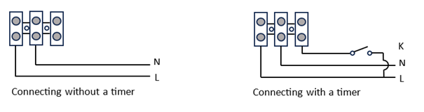
Click here to open the wiring diagram
Settings
The humidity level and timer are adjusted using two moisture-protected potentiometers. It is recommended to make adjustments using the supplied plastic screwdriver.
The selected humidity level is indicated by an LED indicator located in the upper part of the unit.
When the humidity exceeds the selected threshold, the fan switches on automatically. When the humidity drops below the selected level, the fan continues to operate until the timer delay expires, then switches off.
When the push-button is pressed, the timer is activated and the fan operates for the selected period, regardless of the humidity level in the room.
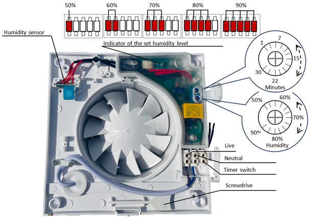
Click here to open the settings diagram